
Contents
The first sign of the problem was this bike would not idle well. I thought the carburetors got dirty and all I needed was to clean them. But, before I started on that task, I decided to check the valves and I found the left intake valve lash was 0.012 inches instead of 0.004-0.006 inches. Hmmm …. how did that tappet get so loose?
Before I reset the valve clearance, as I always do, I torqued the cylinder stud and head bolt nuts to 25 Ft/Lbs. But, one stud just spun. Bummer. That means the threads in the engine block are stripped.
It turns out a friend of mine, Dick, had the same problem on his 1972 R75/5 a couple of weeks earlier. I contacted him and learned he made arrangements to rent a jig to repair his stripped threads from Northwoods Airheads. So, we jointly repaired our stripped threads in “Brook’s Airhead Garage” when the jig arrived. This write-up is based on the work we did on both bikes.
Parts
In addition to the Heli-Coil insert supplied by Northwoods Airheads, we installed the following parts.
| Qty | BMW Part# | Description |
| 1 | 11 11 1 255 001 | BASE GASKET 1970-75 |
| 2 | 11 32 1 250 267 | PUSH ROD TUBE SEAL 15mm |
| 1 | 11 12 1 338 715 | CYLINDER HEAD GASKET |
| 2 | 07 11 9 934 460 | SNAP RING – C22X1,5 |
| 1 | 11 13 1 338 427 | PAN GASKET |
You have to remove the oil pan to clean out all the aluminum shavings, aks swarf, from the drilling and tapping of the engine block. I opted to reuse my pan gasket but Dick replaced his as it was leaking. We both opted to replace the pushrod tube rubber seals as they are inexpensive and mine have been in service for more than six years. It would suck to get the top end back together and have them leak.
Tools
The required jig is available for rental from Northwoods Airheads. Included is a 20 mm long M10x1.5 Heli-Coil insert. Other tools you need are:
- a torque wrench,
- standard metric sockets,
- box end wrenches,
- feeler gauges for setting the valves, and
- a gasket scraper.
On this project I tried out a new set of hard plastic scrapers available from Bike Master. These are hard enough to remove gasket sealant but soft enough they won’t gouge the aluminum.
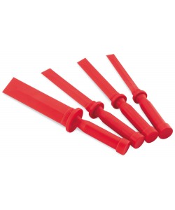
Biker Master Hard Plastic Gasket Scrapers
On Dick’s oil pan, some hardened gasket is in place and the plastic scrapers can’t entirely remove all of the bits so some carefully scraping with a gasket knife is required.
Remove the Top End
The procedure is no different than what you do to replace push rod tube seals. You can see how this work is done on my 1975 R75/6 with my son Branden: there is no difference in the procedure for /5 or /6 bikes:
–> Silver Ghost Restoration-Part 3 Engine
NOTE:
When I remove parts I put them in labeled plastic bags. I label the push rods showing intake or exhaust and which end was at the top engaging the rocker arm assembly. It’s better to install the push rods with the same end on the rocker arm assembly and the cam follower.
NOTE:
Some of these pictures are from my R75/6 top end disassembly as they are applicable to the /5 top disassembly as well.
-
Set Engine to Top Dead Center
This moves the piston to the end of the cylinder making it easy to disconnect the piston from the connecting rod and leave the piston and rings in the cylinder.
-
Remove Valve Cover

Remove Valve Cover
-
Remove Exhaust
Removing Muffler From Bracket
-
Remove Carburetor
You can keep the carburetor attached to the throttle and choke cable, which is what Dick did. I removed mine so I would have plenty of room to work on the stripped hole since it was at the rear of the cylinder next to the carburetor. Either leaving the carburetor attached to the cables or removing it worked okay while using the jig.
Carburetor Removed
-
Remove Intake & Exhaust Rocker Assemblies
I loosen the head nuts incrementally in a cross-wise pattern so I take pressure off the head evenly avoiding any chance of warping the head. I also back off the tappet adjusting nuts and back out the tappets so when I install the head there will be no pressure on the push rods.
Put each rocker assemble and it’s head nuts in it’s own zip lock bag labeled “Intake” or “Exhaust”. Put a piece of masking tape at the top on each push rod with “Intake-Top” or “Exhaust-Top”.
Loosen Rocker Arm Nuts in A Cross Pattern
Pulling Rocker Arm Assembly Off
Bag Rocker Arm Assemble in Labeled Bag and Label Push Rod Including Which End is Top
-
Remove Head
You may have to use a rubber mallet to get the head to come loose from the cylinder. A couple gently taps should do it; you don’t want to break a fin.
Remove Head and Head Gasket From Cylinder
-
Remove Cylinder
You may have to use a rubber mallet to get the cylinder to come loose from the engine block. A couple gently taps should do it; you don’t want to break a fin.
Removing Cylinder From Engine Exposing Wrist Pin in Piston
-
Remove A Wrist Pin Clip-Slide Wrist Pin Off Connecting Rod
In the above write-up, I removed the piston from the cylinder and connecting rod since I was going to replace the rings. But for this repair I leave the piston in the cylinder and avoid disturbing or possibly breaking the rings when I have to reinstall the piston into the cylinder.
I pull the cylinder far enough out to expose the wrist pin hole in the piston, but not far enough to expose the rings. I remove one wrist pin clip (I prefer to remove the rear one) and push the wrist pin far enough out to release the piston from the connecting rod. The piston stays in the cylinder with the rings in the bore.
Wrist Pin Pulled Far Enough To Leave Piston In Cylinder
Remove Cylinder Stud From the Block
Before removing the cylinder stud from the damaged thread in the engine block, I measure the exposed length of all the rods from the base of the engine block where the base gasket goes. The measurement varied between 9-15/16 and 10 inches (252-254 mm) which is within the specification. I want to check them all in case the one with the pulled thread had moved out or into the block.
When I install the cylinder stud, I aim for 9-15/16 in (252 mm). I need enough exposed cylinder stud thread on the end so there is enough thread for the stud nut to hold the rocker arm firmly in the head.
Cylinder Stud Length From Base of Engine Block, 9-15/16 to 10 Inches, (252-254 mm)
Cylinder Stud Length From Base of Engine Bock
Dick only needs two M10x1.5 nuts to remove the cylinder stud from the damaged hole.
Double Nut to Remove Cylinder Stud (Use Triple Nuts if They Spin)
I have to use three nuts on my cylinder stud to back it out of the engine block. When I use two nuts, they spin on the threads. Using three and then putting my box end wrench on the outer nut got the cylinder stud to back out of the engine block. When it comes out, the reason it was so hard is clear as the threads are still attached to the rod. Trying to extract the rod caused the threads to jam making it much harder to twist the stud out of the block.
Cylinder Stud with Aluminum Thread Attached
Aluminum Thread “Cocoon” Removed From Cylinder Stud
Aluminum Thread After Removing From Cylinder Stud
I clean the threads on the stud with a wire wheel and inspect the threads for any damage using a magnifying glass. They are intact and show no sign of damage and I can easily spin an M10 nut on the threads. If there is thread damage, you need to get a new cylinder stud since you don’t want a damaged thread to fail under stress or to damage the Heli-Coil insert.
How To Use The Northwoods Jig
I shot a short video of how to use the jig to repair the damaged threads in the engine block.
Below are some pictures I took while using the jig with some additional details of the work. The jig worked quite well and drilling out the damaged threads, or what was left of them, and tapping the hole for the Heli-Coil insert didn’t take very long.
In the picture below, left to right:
- Heli-Coil Insertion Tool
- 13/32 Drill Bit
- Heli-Coil Tap
- 20 mm long M10x1.5 Heli-Coil Inserts
- Cylinder Bore Plug
- Drilling Jig with Bushings
- Large Flat Washers
- Tubes For Holding Drilling Jig Tight on Engine Block
Northwoods Airheads Cylinder Stud Thread Repair Jig
The two upper cylinder studs are in holes in the engine block that have an oil passage drilled near the front of the hole at the 12:00 position. It connects to the holes in the cylinder and head the cylinder stud fits inside of. Oil flows in the annulus between the hole in the cylinder and head and the cylinder stud to lubricate the rocker assemblies in the head. The two bottom cylinder stud holes in the engine block do not have oil passages so you don’t need to worry about getting swarf into those oil passages.
DANGER:
YOU DO NOT WANT TO PLUG THE OIL PASSAGE NEXT TO THE UPPER CYLINDER STUD HOLE WITH SWARF NOR COVER IT WITH THE HELI-COIL INSERT.
Upper Cylinder Stud Holes Include An Oil Passage In The Engine Block at 12:00 Position
I soften some candle wax using my heat gun. Then I press a gob into the oil passage. This keeps swarf from getting into the oil passage when I drill out the old thread. After drilling, I remove the drilling jig, and check the oil passage. The candle wax is gone so I use a small piece of wire to probe the oil passage and didn’t find any swarf in it. I put another gob of softened candle in the oil passage before I tap the hole for the Heli-Coil insert.
Softened Candle Wax To Plug Oil Passage
Softened Candle Wax Pressed Into Oil Passage
The cylinder bore plug fits over the connecting rod. Be careful you don’t let the rod drop onto the engine case and nick it when inserting the plug as this will lead to oil leaks from the base of the cylinder.
Cylinder Bore Plug Installed
I insert the 13/32 in. bushing into the hole of the jig that lines up with the hole I need to drill out. The other bushing is for the Heli-Coil tap and goes in the other hole to secure the jig on the three remaining cylinder studs. I twist both bushings so the lip on each is snugly under the set screw securing them into the drilling jig.
NOTE:
The cylinder stud distances are asymmetric vertically vs. horizontally so the jig has to be rotated to fit over the remaining cylinder studs.
Drill Bushing For 13/32 Drill Bit Installed in Boring Jig
Installing Boring Jig on (3) Remaining Cylinder Studs
I push the drilling jig over the cylinder plug until it is snug against the face of the engine block.
Drilling Jig Installed on Engine Block and Around Cylinder Plug
Drilling Jig Installed on Engine Block and Around Cylinder Plug
The two tubes fit over two of the remaining cylinder studs that are on a diagonal from each other. The large washers go on top of the tubes and are secured with two existing cylinder stud nuts, hand tight to snug the drilling jig to the engine block. You do not need to tighten them with a wrench which could distort the tubes. Very snug, finger tight, will do it.
Tubes With Flat Washers Go On Opposing Cylinder Studs
Existing Rocker Arm Stud Nuts Secure Tubes to Face of Drilling Jig
The crankshaft is right behind the stud holes in the engine block so you don’t want the drill bit to go any deeper than 58 mm.At that depth the drill bit will cut out the threads but not run into the crankshaft. I use a piece of tape to mark the drill bit and drill into the engine block until the tape just meets the face of the 13/32 in. drill bushing.
Setting 58 mm Depth For 13/32 in. Drill Bit
Setting 58 mm Depth For 13/32 in. Drill Bit Using Tape on Drill Bit
I confirm the drilling jig is flush to the engine block, is tight and won’t move.
Checking Boring Jig Is Tight on Engine Block
I put several globs of axle grease inside the bushing. This will catch a lot of drill swarf minimizing the amount that will fly around inside the engine so clean up should be easier. It also lubricates the drill bit.
Axle Grease Inside Drill Bushing Catches A Lot of Swarf-Lubricates Bit
Any electric drill will work. The bit may catch on the remaining threads and twist the drill hard, so go easy and if the bit binds, run the drill backward to free the bit and then continue.
Drilling Out Damaged Cylinder Stud Threads in Engine Block
After drilling up to the tape on the bit, I remove the drilling jig and clean out the swarf and remaining grease in the hole.
Drilled Out Cylinder Stud Hole in Engine Block
I switch the drill bushing with the tap bushing (marked 12 . 20) so the tap bushing will be over the hole.
Heli-Coil Tap Bushing
There isn’t a lot of clearance to use a tap T-handle. I use a 1/4 inch drive 5/16 inch socket with a 3/8 inch adapter to fit my 3/8 inch ratchet handle. It’s easy to use the ratchet to drive the tap into the hole.
5/16 Socket with 1/4-to-3/8 Ratchet Adapter for Driving the Tap
Socket With Ratchet To Drive The Heli-Coil Tap Into The Block
Before installing the drilling jig, I put another gob of softened wax into the oil passage. Then I attach the drilling jig and secure it to the face of the engine block with the two tubes and cylinder stud nuts. I put another couple gobs of axle grease into the tap bushing to catch as much swarf as I can in the grease and to lubricate the tap.
Axle Grease Inside Tap Bushing To Catch Thread Swarf and Lubricate The Tap
I turn the tap a full revolution into the block and then back it off 1/4 turn to break off the aluminum thread shaving. After driving the tap about four full turns, I remove it and clean the swarf off the flutes of the tap and put more grease gobs into the bushing and continue to run the tap in another four full turns. Rinse and repeat.
I put a tape marker on the tap at 58 mm so I know when the hole is tapped all the way.
Using Socket Ratchet To Tap The Hole for Heli-Coil Insert
Axle Grease Traps A Lot of Heli-Coil Tap Swarf
I use a flashlight to visually inspect the new threads to be sure they go all the way through the hole. Then with my finger over the hole on the inside of the engine, I run the tap in one more time until I can feel the tap coming through and can verify that the full thread width of the tap has cleared the end of the hole. Any small bits of swarf stick to my finger which keeps them from falling into the engine. I remove the jig and clean up the tapped hole removing any grease with trapped swarf still in the hole.
BMW recommends that the Heli-Coil insert have very strong red Loctite applied before installing it. This is not what is usually done with a Heli-Coil insert but BMW recommends it so I follow their advice.
Before I install the Heli-Coil insert, I clean the tapped hole with acetone on some Q-tips to get all the grease off of the threads and I also clean the outside of the Heli-Coil insert threads with acetone as they engage with the tapped threads in the engine block.
I use Loctite 271, but I am told Loctite 263 is also recommended. Both take 10 mins to set up which is what you want so it doesn’t set too fast. Loctite 263 maybe easier to find.
Q-tips with Acetone to Completely Clean Heli-Coil Tapped Threads
The Heli-Coil has a tang on one end that fits into the slot of the installation tool. I twist the installation tool to screw the Heli-Coil insert into the tapped hole.
Heli-Coil with Loctite On It Attached to Installation Tool
Installing Heli-Coil Into Tapped Threads
DANGER:
The first coil of the Heli-Coil insert MUST be just past the end of the oil passage or it will block the oil flow. Further, you do NOT want to drive the insert too far or it will protrude out of the engine block on the back side.
When the first Heli-Coil insert thread is flush with the face of the block, I go slowly and check how far the first thread has gone into the block. I use my other hand and feel for the Heli-Coil coming toward the end of the hole inside the block. I stop driving the insert when all of the first thread is just past the end of the oil passage.
Heli-Coil Threaded In So First Thread Starts Just Behind Oil Passage
What To Do When A Heli-Coil Fails To Thread Correctly
Dick drove his Heli-Coil insert too far into the block and several threads were past the end of the hole near the crankshaft. In an attempt to it back out a bit, he tried twisting the insertion tool in the opposite direction to see if he could unthread the Heli-Coil a couple turns. But, the first thread of the Heli-Coil popped out of the threads in the engine block and jumped one thread away. Not only did this not back the Heli-Coil insert out any, it guaranteed that the cylinder stud could not be threaded into the Heli-Coil insert.
It took more than a day to figure out what to do about this problem. And during that time the Loctite setup. This formula of Loctite requires 500 F temperatures to loosen up so you can back off a threaded fastener. Gulp !!!!
I lean that acetone dissolves hardened Loctite. So I use an eye dropper and Q-tips to flood the Heli-Coil insert with acetone multiple times. Since a Heli-Coil is a stainless steel spring, there is a gap between the coils and I hope the acetone will eat away the Loctite between the coils of the spring and then penetrate down into the tapped threads in the block.
After several acetone baths, I use a jewelers screw driver to get under the first thread, about a 1/4 turn from the end where it is sitting on top of one of the tapped threads. I manage to bend it up a bit. I bent it further with a bigger screw driver so it can be gripped with needle nose pliers, or better yet, needle nose vice grips. I only have pliers, but I think needle nose vice grips would have been better. I twist the end of the insert counter-clockwise which winds it up so it tightens up into a smaller diameter. I was happy to see it pulling away from the tapped threads in the engine block which means the acetone dissolved enough of the Loctite that the Heli-Coil comes loose without damaging the tapped threads in the engine block.
Using Needle Nose Pliers to Remove Heli-Coil
The insert comes out in two pieces.
What’s Left of Heli-Coil After Removal
I use the jig to run the Heli-Coil tap through the hole to chase the threads. Then I install another insert and let the Loctite setup over night.
Install the Cylinder Stud
Before I insert the cylinder stud I have to let the Loctite harden for at least 24 hours. After 24 hours, I remove the tang on the end of the Heli-Coil inside the engine block. I use a screw driver to bend it back and then I use a long reach, narrow needle nose pliers inside the hole to grab the tang and flex it in and out while I hold a finger over the tang inside the engine. When the tang snaps off, I push the tang into the hole and use a pick to fish it out.
Heli-Coil Tang After Its Broken Off The End Of The Insert
But, Dick’s tang falls into the engine block. No worries. We will clean out the inside of the engine to remove the swarf and most likely the tang feel into the oil pan and will be easy to find.
WARNING:
If the tang falls inside the engine, be sure you locate it after you remove the oil pan.
I install the cylinder head stud into the hole with the Heli-Coil insert and set the depth to 9-15/16 inches (252 mm) so I get as much thread engagement in the block as possible. Dick’s stud is not completely snug in the Heli-coil, but after consulting with Tom Cutter at Rubber Chicken Racking Garage, he felt it will snug up when it is torqued and not to worry about it. I suspect the tapped hole was just a tiny bit enlarged after removing the Heli-Coil and chasing the threads with the tap.
My stud feels as snug in the block as the original studs. It seems a bit of looseness of the stud is not a cause for concern.
Clean Swarf From Inside the Engine
Now the inside of the engine has to be cleaned to ensure no swarf is left inside.
The first thing I do is use a curved piece of fine wire to get inside the oil passage in the engine block to see if there is any swarf. I did find a tiny bit and cleaned it out. Then I insert the tube on my brake cleaner can inside the oil passage toward the top of the passage and gently squirt some brake cleaner inside the passage until it flows out. I see no swarf come out.
Next, we drain the oil as we are going to remove the oil pan to get access to the inside of the engine block.
Draining Oil Prior to Removing Oil Pan
I always put red tape on parts that need attention. So when I drain the oil from the engine, I put some tape on the dip stick.
Red Tape Means No Oil
I find a glob of grease with swarf in the bottom of my pan. That is a good sign that using axle grease minimized the spread of swarf inside the engine. And, in Dick’s pan we want to insure the tang from the insert is out of the engine. We find it in the bottom of the oil pan. 🙂
Gob of Grease with Swarf in Bottom of Oil Pan
NOTE:
When you pour the oil out of the drain pan, go slow because if your Heli-Coil tang fell into the engine, it may end up in the drained oil and you want to put your hands on it to ensure you know it’s not inside the engine.
I remove the cam followers to be sure no swarf ended up on the cam shaft or got lodged between it and the follower. I use a small paper clip with some wrinkles in it and insert it into the oil hole in the center of the follower and pull it out.
WARNING:
It’s not a good idea to use a magnet to remove the follower as that will magnetize the follower and it will tend to attract small particles of steel circulating in the oil and that can damage the face of the cam and the follower. That’s why I use a paper clip to remove a cam follower.
Paper Clip For Removing Cam Follower
Using Paper Clip to Remove Cam Follower
Cam Follower Surface Inspection – All Good
I keep the cam follower matched to the cam lobe it rides on so I put each in a bag labeled intake and exhaust. Then I put the long stinger on my air chuck, insert it into the cam follower hole and blow air across the cam to dislodge any swarf that may be there or on the cam shaft.
Long Stinger on Air Chuck For Blowing Out Swarf
Blowing Air Through Cam Follower Hole to Clean Off Cam Lobes
The strategy is to start at the top of the engine and work down as we blast compressed air inside the engine. The idea is any swarf that’s dislodged will tend to fall down and out of the engine block rather than go up.
We use a strong light source to look inside the engine block. Small bits of aluminum swarf will be reflective and we can see small bits easier. We use a small inspection mirror to look around inside and we also rotate the crankshaft a 1/4 turn each way from top dead center so we can access and blow out hidden parts of the crankshaft better. I find some small aluminum swarf in the gap between the connecting rod big end and the crank journal in Dick’s bike.
Using Strong Light To Look Into Engine After Oil Pan Removed
Shelf Where Swarf Will Hide So Blow Out All Along the Edge
From the bottom of the engine, looking up, I use the air chuck to blow out around the lip on the bottom of the block where the oil pan holes are as this is a great place for swarf to hide. We clean off the top of the oil pump pick up with a rag.
Lots of Light For Finding Aluminum Swarf Inside Engine Block
Cleaning Top of Oil Pickup Housing
Then we do this procedure one more time, starting at the top and moving to the bottom of the block. And then a third time. And on the third time I find a small bit of swarf and grease on the top of the casting that the cam follower fits inside of on my bike.
On the fourth time, we don’t find any signs of swarf so we call it good.
NOTE:
Don’t be in a hurry to finish up the cleanup of swarf inside the engine. Take your time and even invite a friend to help you look around. Four eyes and two brains are better than one in ensuring you get it all.
Install Oil Pan and the Top End
The procedure to clean and install the oil pan, and assemble the top end can be found here:
If you didn’t remove the piston and/or the rings from the piston, you don’t need to reinstall them.
WARNING:
If you leave the piston in the cylinder, be sure to check that the arrow stamped in the top of the piston is pointing to the front of the bike. Although unlikely, it is possible for the piston to get rotated in the cylinder before you install it back on the connecting rod.
Correct Left Side Piston Orientation with “Vorn” Arrow Pointing to Front of the Bike
For this work we tested the oil flow through the cylinder stud hole in the engine block with the repaired thread to be sure the oil passage was not blocked and oil flowed all the way to the head. There is a short video of that test a bit later.
Here are some pictures from our work installing the oil pan and top end on Dick’s and my bike.
Clean Oil Pan
Installing Oil Pan Bolts
Scraping Sealant From Cylinder Base
Scraping Sealant From Engine Block
Cleaning Engine Block with Acetone
Installing Base Gasket with Sealant On Both Sides
Head Gasket Installed Correctly on Cylinder
Cylinder, Head Gasket and Head Installed
Installing Push Rod (Note Tag Indicating The Top End of the Rod)
Push Rods Installed
Rocker Block Installed With Correct Orientation
Checking Push Rod Tube Rubbers Are Seated and Oriented Correctly
Testing Oil Flow to Head
After installing the base gasket, cylinder, head gasket and head, but before torquing the head bolts to 23 Ft-Lb, I want to test the oil flow from the top cylinder stud oil passage in the block to be sure it’s clear. Even though I am pretty sure there is no blockage in the oil passage, I want to prove it.
I snug the head bolts to about 5-10 Ft-Lbs to pull the cylinder and head snug to the block and set the push rod tube rubbers. Then I remove the rocker assembly the cylinder head stud with the repaired threads connects to (the rear one next to the carburetor). I remove the spark plugs and the green wire from the coilds so they won’t be energized when I use the starter to crank the engine and pump oil to the head.
Pulling Green Wire From Coils To Prevent Damage During Cranking
DANGER:
If the the spark plugs are not connected to the cylinder and the spark plug cap, and the green wire that energizes the coil is connected to the coil, energy in the primary winding of the coils will arc to the secondary windings when the points open and can damage the insulation on the coil’s wires since there is no ground via the spark plugs for the energy to dissipate. And, if you have an electronic ignition, you will likely destroy it.
I always put red tape on parts that need attention. So when I drained the oil from the engine, I put some tape on the dip stick. I put fresh oil in the engine before I test the oil flow to the head and remove the red tape..
Red Tape Means No Oil
Here is a short video of how I tested the oil flow to heads from the repaired threads of the upper cylinder stud rod that had stripped its threads.
After the successful test, Dick torqued the head in three stages using a cross-wise pattern to 23 Ft-Lbs.
Bringing Up Torque on Cylinder Studs in 3 Stages
Then he attached the exhaust system and carburetors.
Installing Mufflers
Completing The Work
After cylinders, heads, and rocker arms are installed, and the oil flow to the head tested, the six cylinder head nuts are torqued in three stages to 25 Ft-Lbs. Since the new head gasket will compress, I like to wait 24 hours before setting the valves. The next day I re-torque the head nuts to 25 Ft/Lbs and then I set the valves to 0.004 in. inlet and 0.008 in. exhaust.
After the valve covers are back on and I’m sure fresh engine oil has been added to the pan (I check the dip stick just to be sure), I go for a 10 min ride (5 miles or so). Then I drain the oil, change the oil filter (and open it to look for any aluminum swarf), drop the pan again and clean it out. I found some larger pieces of aluminum swarf in the bottom of the pan still congealed in some grease. I also saw a couple small flecks of aluminum swarf on the oil filter. But, all cleaned out now.
I’m glad I just ran the engine long enough to get the oil hot and then drain it and the pan. This ensures any small bits of swarf that escaped the first cleanup are now safely out of harms way.
Revisions
2018-11-26 Minor edits.
2019-01-02 Add cylinder stud exposed length in mm.
2019-02-08 Add warning about correct piston orientation.
2021-04-13 Corrected cylinder head nut torque value to 25 FT/lbs.
Another great write-up! Thank you.
Hi Sanders,
You are welcome.
Best.
Brook.
I celebrate your excellent writeup
Re: the Heli-Coil tangs. These are to provide purchase to screw into the threaded hole, right? Why can’t they be left intact?
Hi Michael,
That’s an interesting question. I found that the stud doesn’t go all the way into the block when threaded in to keep 9-15/16 to 10 inches exposed. There is about 1/4 inch of threads not engaged at the bottom of the hole in the engine block. So, the tang will not interfere with the cylinder stud when it is threaded it.
However, the tang has a notch cut in it to allow it to snap off. What concerned me is that vibration over time would cause the tang to snap off and fall into the engine while it was running. If that happened, expensive, bad things can happen.
My recommendation is to remove the tang and retrieve it so there is no possibility of it falling out later.
Best.
Brook.
This is a very detailed description of the procedure. With careful attention to this detail anyone who can use tools should be able to do the repair. It is wonderful that the kit may be rented for this hopefully one time repair. Henry Tupper, machinist.
Thanks Brook for another interesting description. The video is great! I have 2 questions:
1. Is the helicoil tang on the inside or outside once inserted (couldn’t see)?
2. I made the mistake of threading my cylinder studs using blue Loctite. Also they were not in the full 9 15/16 inches. What do you recommend?
Hi Ken,
The tang is on the inside of the block since it is the on the first coil to thread into the block.
You don’t mention why you removed the studs from the block. I hope all four didn’t end up with stripped threads.
If your studs are more than 10 inches out of the block I would remove them and set them to the correct length and remove the blue Loctite.
I would try heating the stud near the block with a heat gun or propane torch to soften the Loctite to make it easier to remove them. Blue Loctite is much weaker than the red version I used to help lock the Heli-Coil insert into the block and it quickly softens with some applied heat. Then clean up the threads in the block and the studs to remove the traces of blue Loctite. Then I would make sure they are between 9-15/16 and 10 inches per the specification. That way, more threads take the torque and stress rather than fewer.
I hope that helps.
Best.
Brook.
Dear Brook,
I noticed that cylinder head doesn’t assembly spacer sleeve and o ring for rocker arm and checked fiche from MAX BMW said that was only used on slash 5 from 2/1970 to 8/1972. May I know why? does spacer sleeve(11 12 1 254 840) and o ring(11 11 1 460 391) is essential for slash 5?
My bike is produced on Oct 1969 as first batch ever built and it also doesn’t came with spacer sleeve and o ring, so I am wondering to know that bike should assembled space sleeve an o ring or not.
Please advise.
Hi Calvin,
I’m not knowledgable about the very early /5 cylinder heads. Perhaps this will help you.
–> http://www.largiader.com/tech/rockers/
It is possible the rocker assembly on your bike was upgraded with a newer design.
I hope that helps you.
Best.
Brook.
Hello Brook, I really enjoy the videos you make on BMW maintenance. Regarding the o-rings that fit into the recess around the collars against which the rocker blocks fit, what stops oil from seeping out of the head? I see on Calvin’s post he mentions the parts fiche shows spacer sleeves to compress the o-ring between the recess and the rocker pillow block. My YoM Oct ‘73 R75/6 is seeping oil from the outside of the tube surrounding the head stud so I’m thinking the spacer sleeve should be there to compress the o-ring into its recess.
So, how does the loose o-ring stop oil seeping out?
Best regards,
Chuck Hamilton
Sydney, Australia
Chuck,
The spacer sleeve (part# 11 12 1 254 840) seals against the o-ring. When you tighten the cylinder stud nut on top of the rocker block, it compresses the o-ring. If the o-ring is damaged or missing, oil will leak.
Best.
Brook.
G’day Brook, thanks for the response. I did notice on your video that you did not install spacer sleeves. How did you seal your o-rings?
Chuck,
The 1973 heads don’t use the O-rings.
Best.
Brook.
Then I don’t understand why the o-rings appear on the microfische.
Chuck,
IIRC, earlier /5 bikes had the O-rings and later ones did not. The mircofiche show all parts used on a model over the years. Some parts descriptions will include when the parts were used on that model, but not always reliably so.
Best.
Brook.
Brook, thanks for the great writeup. Any reason you chose Heli-coil instead of time sert?
Thanks again.
Hi Marteladam
Yes, it is recommended for this application by several very knowledgeable airhead mechanics, and it is what is supplied by North Woods with the tool. The Timesert type repair has a “top hat” and a small groove needs to be cut for it to lay flat. That’s problematic with the top cylinder stud holes as they are passages for oil flow to the rocker arm.
Best.
Brook.
Brooks-thank you for all your help with the BMWs. After the rear oil passage is tested, do you repeat the process for the exhaust oils passage?
Hi Dave,
Both top cylinder stud oil passages are connected to each other via a common horizontal oil galley. So, you should see oil flow from both top studs. If not, there maybe debris in the oil galley passage. I’d try compressed air on one hole to see if you can blow it out the other.
I hope that helps.
Best.
Brook.
Brook, please excuse me if I missed this somewhere in your write up, but do you recommend putting any copper anti seize or any other lubricant on the cylinder studs before installing in the block? and thank you for the excellent write up, as always.
Hi Andrew,
From about 1/2 way down the page:
“I use Loctite 271, but I am told Loctite 263 is also recommended. Both take 10 mins to set up which is what you want so it doesn’t set too fast. Loctite 263 maybe easier to find.”
You need to lock them in place, so you do NOT want anti-seize on the threads.
I hope that helps.
Best.
Brook.
Forgive me for asking a clarifying question. I understood from the article that the comment related to Loctite was about locking the Helicoil insert in the block, rather than locking the studs into the newly repaired threads. Should I use Loctite for both fixing Helicoil into the block, and when inserting the studs, fix them too with Loctite into the Helicoil?
Lauri,
I believe I only loc-tite the helicoil into the engine block.
Best.
Brook.
Hello Good Morning Mr. Brook, I removed the cylinder studs because of I had to Vapor blast the engine.
All the threads of the holes we’re perfectly intact.
When reassembling the studs I noticed that I had to use some force to screw them in.
As if the thread were dirty or very tight.
I tried to pass an M10x1.5 threading male (# 2) and after doing it the stud screws perfectly but it remains slow.
I mean that once screwed to the right depth the cylinder stud stays slow. I can easily rotate it with my fingers and moving it sideways has play. Is that a problem? Should I perhaps insert a helicoil?
Francesc,
If the cylinder studs feel loose in the holes, I would use the red loctite I used when I repaired the stripped threads in the engine block. This should lock the studs into the engine block.
I suspect when you ran the tap through the threads, you removed some metal which made the stud loose in the threads.
Best.
Brook.
Hello Brook,yes it was not a good idea to use the tap. What you wrote certainly happened. Thanks so much for the reply.
Hello Mr. Brook,
If possible I’d like to have your advice.
What is the correct procedure to re-assemble the cylinder studs?
It is necessary to screw them by hand or with a double nut until reaching the correct distance from the engine case (i.e. 253/254mm for all the studs), then mount the cylinders, the heads and then tighten the head nuts to the correct torque according to the sequence 10- 18-25 foot-lbs?
Or do you have to partially screw the stud in and proceed to tighten the head nuts, checking that once the 25 foot-lbs torque is reached the studs are at the right distance?
Referring to a quetion I wrote to you some years ago, If a stud is loose in the engine case thread, is there a risk that by tightening the nuts the stud could enter in the engine case more than necessary? If so, how can the problem be resolved? Thank you very much.
Francesco,
The cylinder studs should not turn when you tighten the head nuts. If they do, the threads are stripped. You will need to repair them as I show here:
–> https://brook.reams.me/bmw-motorcycle-rebuilds/1973-bmw-r755-rebuild-project/11-bmw-r75-5-repair-stripped-cylinder-stud-threads/
The studs are installed with red loctite so they won’t turn when you torque the nuts.
Best.
Brook.
Hi Mr. Brook, the threaded holes of the engine case for the cylinder studs are ok.
Only one, the one in the right cylinder at the top right, was accidentally reworked years ago with an M10x1.5 threaded insert with the result that the threaded tap most likely removed some material.
Infact, I noticed that the stud was screwed in by hand very easily, without friction, and once the correct distance of 253-254mm was reached, the stud could still be screwed in by hand and by shaking it moved vertically and laterally.
Before having my mechanic reassemble the engine and cylinders, I asked him to fix this problem.
Although the engine has never been run since it was reassembled (it is all new and dry with no traces of oil) yesterday I removed the heads to check the squish band and noticed the stud still loose.
My mechanic didn’t do what I asked him to do.
My concern is that by reassembling the head and tightening the head nuts the stud may enter the engine case more than it should.
I was advised to remove the stud, leaving the cylinder in place, and use a thin layer of loctite (ok the red one?) on the threaded part that goes into the engine case but I’m afraid that the loctite could block the exit hole of the ‘oil.
Unfortunately I have the cylinders and pistons assembled and would not like to remove them.
Since I can unscrew the stud by hand, do you think I can remove the stud, apply the loctite and reinsert it into the cylinder and then wait for the loctite to harden and then reassemble the head and tighten the nuts?
Hmmm … sounds like you need to install a helicoil for that loose stud.
Best.
Brook.
Hmmm .. I want to cry ahahahahhaha