As I had the engine stripped down, I was able to lift it into the frame by myself using some straps so my hands weren’t under the oil pan. The transmission isn’t very heavy, but there isn’t much clearance when the engine is installed and I had to remove the kick start lever or it wouldn’t fit.
Here are a couple pictures from the write-ups.
Engine Installation
Polished Engine Ready to Install Into The Frame
Engine In Frame Resting on Motorcycle Lift
Left Side Shackle Keeps Side Stand on Pivot Pin (Looking Toward Rear)
Engine In Frame & Secured to Lift
Transmission Installation
Refinished Transmission Ready to Install in the Frame
Clutch Throw Out Assembly Parts
Frame Protection Before Inserting Transmission In the Frame
Clutch Throw Out Bearing Assembly Showing Direction and Order of Insertion into Bearing Housing
The wheels are the next project to work on. The plan is to take them apart, replace the chrome spokes and nipples with stainless steel spokes, inspect, lube and set the preload on the wheel bearings. I decided to have Woody’s Wheel Works inspect the bearings and lace up the new spokes. Here is a link to the write-up on this work.
When I removed the bearing cover on the rear wheel, the left side bearing outer race had loosened and spun in the aluminum hub. There are various options to fix this including:
1. Using locktite on the outside of the outer race to secure it to the aluminum hub.
2. Staking the outer race to try and keep it captive in the aluminum hub.
3. Adding a shim around the outside of the outer race so it is captive in the aluminum hub
4. Buy a new hub.
Option 4 is expensive and since new hubs are no longer available from BMW, is not a viable option.
I also got a response from two folks in Australia with a variation on shimming the outer race. Their fix uses a thin steel sleeve called Speedi-Sleeve, provided by SKF bearing company. It is designed for use on shafts that have been scored by the shaft seal. Adding a Speedi-Sleeve stops the oil leaking past the seal and retains use of the original oil seal. The sleeve that fits the R75/5 wheel bearing is #99157. It’s 0.28 mm or 0.011 inch thick so it adds 0.56 mm or 0.022 inch of material to the aluminum hole holding the bearing. It is installed on the outer race with a special tool. Then the bearing stack is assembled using the axle with a spacer and is put into the heated aluminum hub. This is the standard procedure for installing the bearing stack into the aluminum hub. When the hub cools, it contracts around the Speedi-Sleeve and outer race shell and should hold the shell captive to the hub. This is the solution I choose and had Woody’s install the Speedi-Sleeve.
Here are some pictures from the write-up.
Rear Wheel, Hub Cap Side
Rear Rim Has Deep Gouges
Brute Force Approach: Using Bolt Cutter to Cut Spokes
Front Rim with Cut Spokes and Hub Removed
Non-Distructive Approach: Removing Nipples with Power Screw Driver
The alternator has 97,500 miles on it, so I decided to replace the brushes. I hadn’t seen evidence of oil leaks from the front crankshaft seal, but it turns out its very easy to replace it when I was replacing the alternator brushes. I also cleaned the rust and flaking paint off the starter motor and then painted it to stop any further rusting.
You can read about what I did on both of these tasks here:
I bought the brushes at Euro Motoelectrics which is here in Denver, CO. I also picked up a hardened bolt to extract the alternator rotor from the tapered nose of the crankshaft.
These jobs went pretty quickly and were straight forward. I found I needed a 200/260 watt soldering iron to remove the old solder and solder the new brushes as they are soldered to a large plate that dissipates heat pretty well. My 140 watt gun wasn’t up to the task.
Old Brushes Removed from Holder
New Brushes Installed
Shaft Seal Puller Installed With Adjustable Pivot Pin Resting on Engine Housing
At this point, the engine work I planned is done. Here is the painted starter motor installed and the engine after polishing up the cases.
When replacing the oil pan gasket, I also cleaned the oil pickup screen and checked to be sure the bolts holding the pickup are tightened to the proper torque, 72 INCH/Pounds, not FOOT/Pounds. I used an INCH/Pound torque wrench on them and also on the oil pan bolts which were set to 70 INCH/Pounds in several stages. These bolts are easy to strip out unless you use an INCH/Pound torque wrench.
I put in new points and a condenser when I replaced the cam shaft seal and replaced the timing plate machine screws with two Allan head cap screws, M4x0.7×10. Now its easy to adjust the timing plate points cam with the centrifugal advance weights installed with a small Allan head wrench. And, I won’t be wallowing out the slot on machine screws as happened in the past.
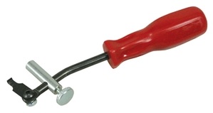
I used my larger adjustable seal puller to remove the camshaft seal, but it makes me nervous since the camshaft seal is small and I don’t want to score the camshaft. After I got the camshaft seal pulled, I looked for a puller for small seals. I found a very promising one, Lisle 58430 shaft seal puller. It’s available at some auto parts stores, but I ordered mine from Amazon.
Lisle 58430 Shaft Seal Puller
I think this will work very well on future seal pulling jobs.
Here are a few pictures of the work.
Replacing Oil Pan Gasket
Engine on Side to Remove Dirty Oil Pan
Permatex Gasket Remover Soaking In
Checking Torque (72 INCH/pounds) on Oil Pickup Bolts
Clean & Polished Pan Mating Surface
Clean Oil Pan with New Pan Gasket
Replacing Camshaft Seal
Leaking Cam Shaft Seal
Points Removed and Timing Plate Ready to Remove
Old Seal
Driving Cam Shaft Seal with 5/8 Inch Spark Plug Socket
I decided to replace the original clutch after inspecting it and measuring the parts. Many were close to, or past, the minimum thickness. You can read about the procedure I used to install the new clutch in this web page: